CAN Interface Firmware
Serial Flux CAN Coyote X7 uses the Serial Flux open-source CAN firmware protocol for supported STM32F072C8 CAN interface devices. Customers do not choose between different application protocols such as candleLight or slcan. A particular device may, however, have multiple hardware-specific builds when different board revisions connect LEDs to different STM32 GPIO pins. Source code and documentation are available from the Serial Flux firmware project on GitHub.
Pico 2 I²C & SPI Controller Firmware
Turn a Raspberry Pi Pico 2 into a USB-connected I²C and SPI engineering interface. The Pico2_I2C_Controller firmware provides separate master, slave, and passive sniffer connections for each bus, supporting development, device testing, troubleshooting, and protocol inspection.
Use Serial Flux (SF) to connect to the Pico over USB CDC, send controller commands, and inspect responses. The companion I²C Logic Analyzer GUI and SPI Logic Analyzer GUI (SLA) provide dedicated bus-capture views. SPI capture forwarding and GUI parsing depend on compatible desktop versions; the text-stream capture protocol remains experimental.
I²C Master / Slave
Exercise and respond to I²C devices using dedicated GPIO assignments.
SPI Master / Slave
Configure clock and SPI mode, transfer data, and debug peripheral communications.
Logic Capture
Dedicated I²C and SPI sniffer inputs for observing bus activity without acting as a bus master.
Raspberry Pi Pico 2 pinouts
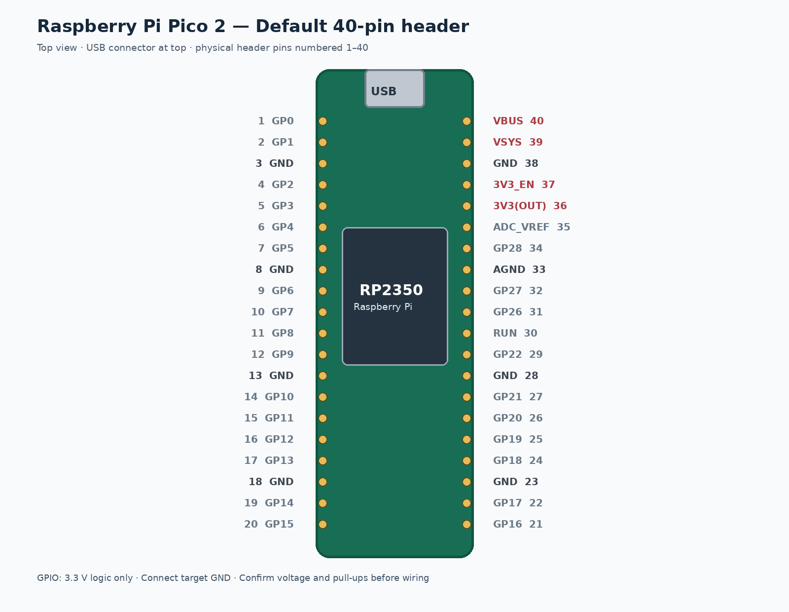
The default RP2350 header layout and firmware-specific GPIO assignments are shown below. Always verify your firmware build and connect a common ground; Pico 2 GPIO is 3.3 V logic and is not 5 V tolerant.
Standard Pico 2 pinout
I²C / SPI firmware pinout
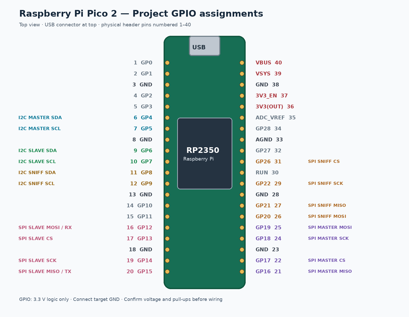
Interface connections
| Mode | Signals and GPIO |
|---|---|
| I²C master | SDA GP4 · SCL GP5 |
| I²C slave | SDA GP6 · SCL GP7 |
| I²C sniffer | SDA GP8 · SCL GP9 |
| SPI master | MOSI GP19 · MISO GP16 · SCK GP18 · CS GP17 |
| SPI slave | MOSI GP12 · MISO GP15 · SCK GP14 · CS GP13 |
| SPI sniffer | MOSI GP20 · MISO GP21 · SCK GP22 · CS GP26 |
Firmware source and setup
The GitHub repository contains firmware source, build instructions, interface documentation, and pinout diagrams. A separate Pico 2 W build is documented; its command transport remains USB CDC, not Wi-Fi.
This firmware uses a separate open-source license. Serial Flux and its companion desktop tools are separately distributed KTY Labs software. Check GitHub for firmware versions and build requirements.